
DPT-150 die pickup tester
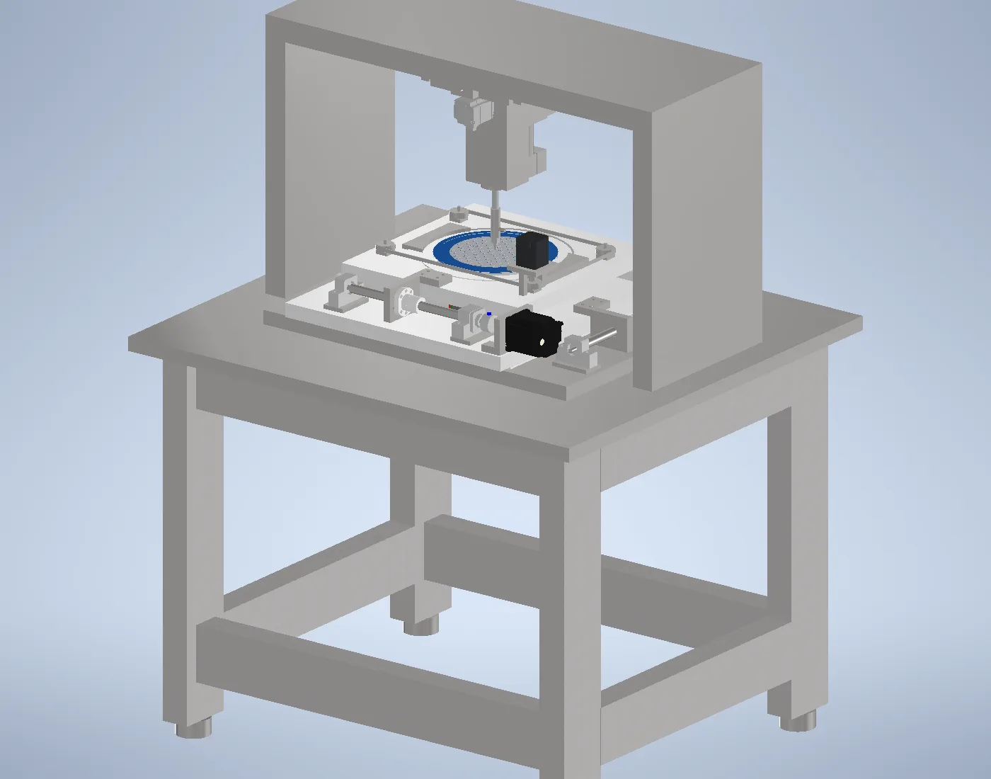
A bench instrument that answers one question: can a singulated die be picked cleanly off expanded dicing tape? Ø150 mm wafers on a standard film frame, one fixed pick point, and an expander, an ejector and a vacuum collet working to it.
- Wafer
- Ø150 mm
- Testable area
- 75% of the wafer
- Smallest die
- 4.2 × 4.2 mm
- Footprint
- 900 × 800 mm
How it works
Three synchronised units work to one fixed pick point. The wafer moves; the head does not. One pass through the five steps is one test, and whether the die releases cleanly is the result.
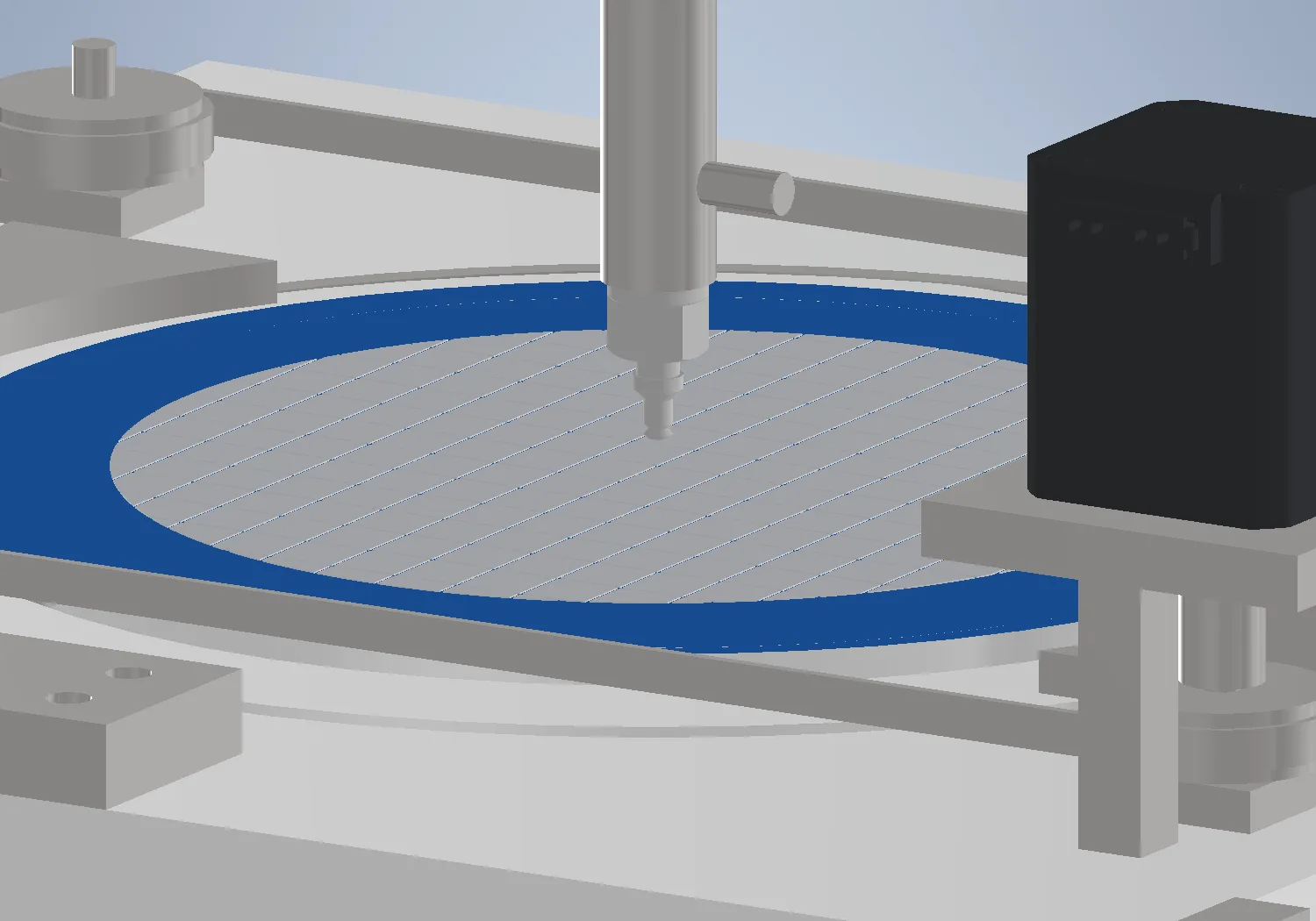
- 1 — Expand
- The film frame drops into the stage. The expander ring rises 6 mm and stretches the tape, opening the gaps between dies.
- 2 — Look
- The camera reads the target die where it lies. The ejector is down, clear of the ring, so the stage can reach any part of the wafer.
- 3 — Position
- The XY stage brings that die to the pick point and the ejector rises under it.
- 4 — Seat
- The head descends onto the die and holds it by vacuum, with the tape still flat.
- 5 — Eject and lift
- Four Ø0.8 mm needles rise 5.0 mm under the tape while the head lifts in step with them, peeling the die off the adhesive.
Wafer and stage
- Wafer
- Ø150 mm, mounted on a standard film frame
- Film frame
- Ø250 mm outside, Ø205 mm bore, 1.5 mm thick
- Reach at the pick point
- Ø129.7 mm disc
- Testable area
- 13,216 mm², 75% of the wafer
- Unreachable band
- Outer 10.1 mm, set by the ejector standing in the ring
- Smallest die
- 4.2 × 4.2 mm square, collet Ø4 plus an alignment allowance
- Stage
- Two orthogonal axes; the pick point is fixed and the wafer moves to it
- Frame loading
- Ring draws 287 mm out of the machine on its guide
Tape expander
- Ring
- Ø188 / Ø198 aluminium hoop
- Rise
- 6 mm
- Drive
- Four Ø8 lead screws on Ø30 pulleys, one belt, so the ring rises square
- Screw ends
- Ø6 ground journal, ball bearing, retaining ring
- Lead angle
- 5.2°, self-locking
- Motor
- Two-phase stepper, 42 mm frame, 0.66 N·m, 1.5 A, 1.8° step
- Torque
- 0.49 N·m needed of 0.66 N·m available, on an estimated tape stiffness
Die ejector
- Needles
- Four Ø0.8 mm, consumable
- Lift
- 5.0 mm
- Park position
- 1 mm below the tape; 2 mm above it at full lift
- Drive
- Servo, Ø24 disc cam direct on the shaft, 2.5 mm eccentric
- Return
- Compression spring, 4.0 N preload, 6.5 N at full lift
- Vacuum
- 80 kPa in a 2.7 cm³ room, drawing the tape onto the hood face
- Guidance
- Two guides 143 mm apart on one turned rod, coaxial by machining
- Sealing
- Rod, static and hood O-rings in machined grooves; bonded washer at the vacuum port
- Needle access
- M38×1.5 hood, 4.7 turns off by hand, no tool
Pick head
- Collet
- Sprung vacuum pad, Ø4 mm face
- Stroke
- 6.0 mm
- Compliance
- Touchdown 2.0 mm before full push — spring, not cam
- Pick force
- 2.3 – 3.9 N, set by the pad fitted and changed by changing it
- Drive
- Servo cam, Ø24, 3.0 mm eccentric, 60 rpm design speed
- Return
- Compression spring, 5.0 N preload, 8.0 N at full push
- Guidance
- Two linear ball bushings 57 mm apart on a turned sleeve
- Anti-rotation
- Ground dowel in a sintered bush, 12 mm engaged
- Park clearance
- 4 mm above the wafer
Installation
- Envelope
- 900 × 800 × 1185 mm
- Frame
- Aluminium profile on levelling feet
- Frame loading clearance
- 287 mm at the ring guide
- Environment
- Indoor, temperature controlled
Standard and premium
| Standard | Premium | |
|---|---|---|
| Wafer stage rotation | None | R axis added |
| Head Z drive | Servo cam — stroke set by the cam | Ball screw — stroke and position set in software |
| Head Y axis | None | Added — the head goes to the die where the camera saw it |
| Ejector | Raised and lowered for every die | Stays up — it rides the head’s Y axis and stays coaxial |
| Pick force | Fixed, set by the pad | Voice coil — force set and varied in software |
| Touchdown height | Not measured | Linear encoder — contact height read on every pick |
| Force measurement | None, pass or fail only | Load cell in the head |
| Wafer stage XY drive | Stepper | Servo |
| Motion control | Standard controller | High-end multi-axis controller |
| Frame | Aluminium profile | Steel base |
Where the two builds differ: motion, sensing and structure.
Views
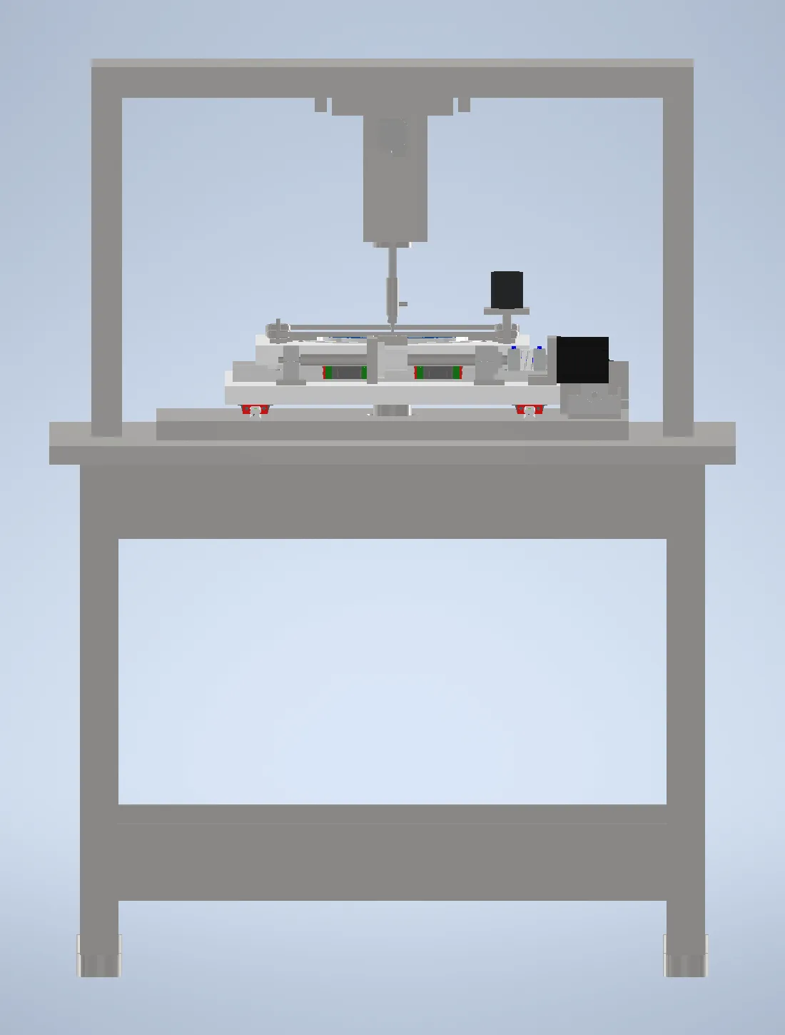
VI 01Front elevation 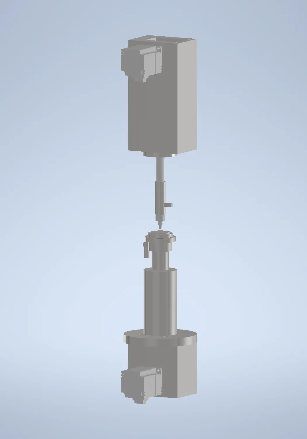
VI 02Head and ejector on one axis 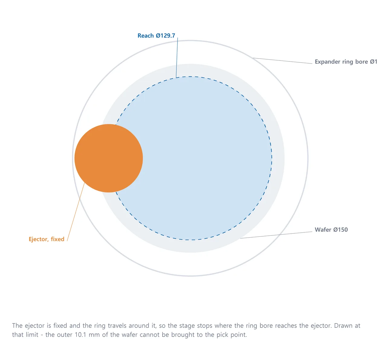
VI 03Workable area, Ø129.7 of Ø150 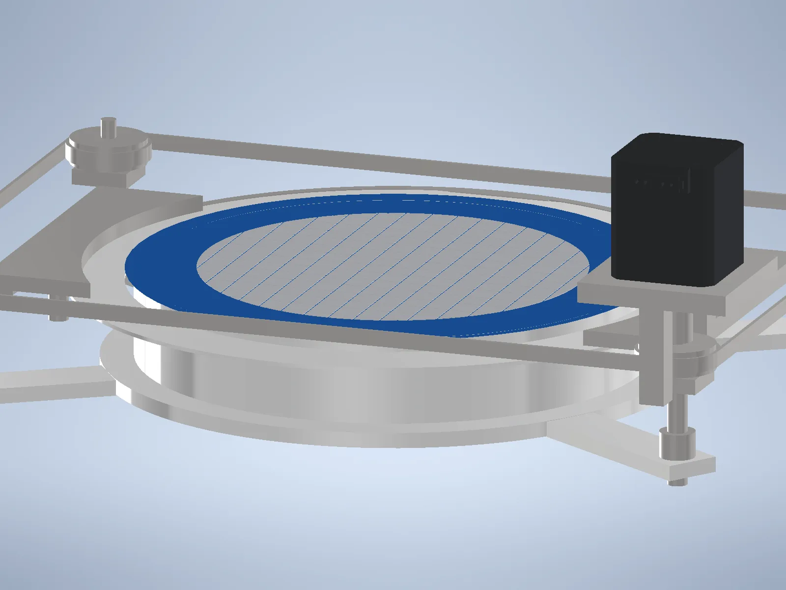
VI 04Tape expander, running 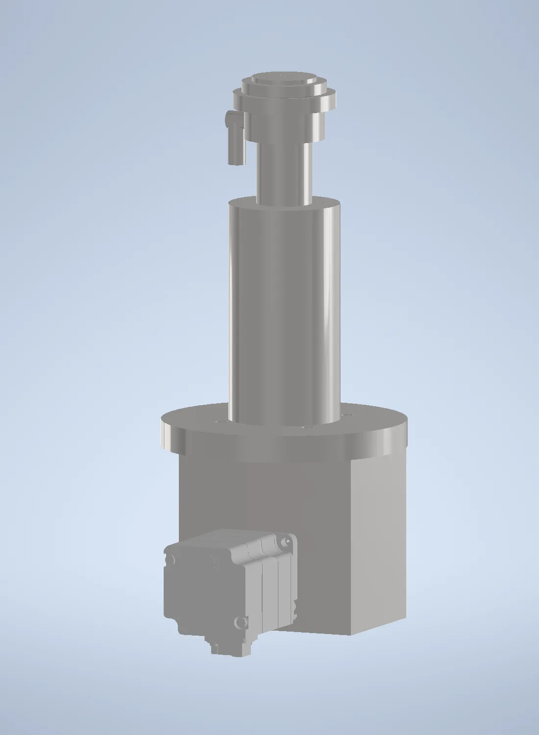
VI 05Die ejector unit 
VI 06Ejector, quarter section 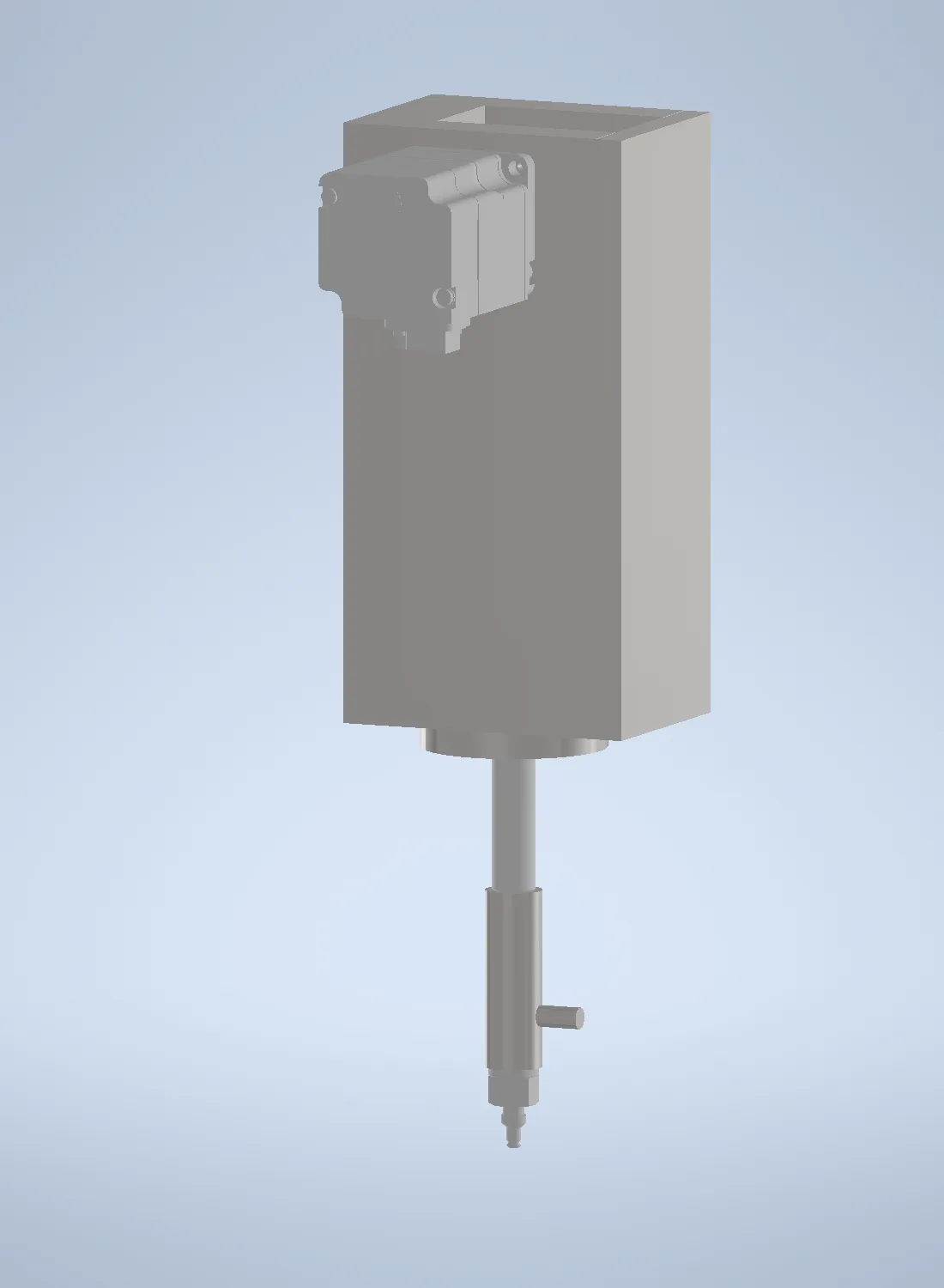
VI 07Pick head unit 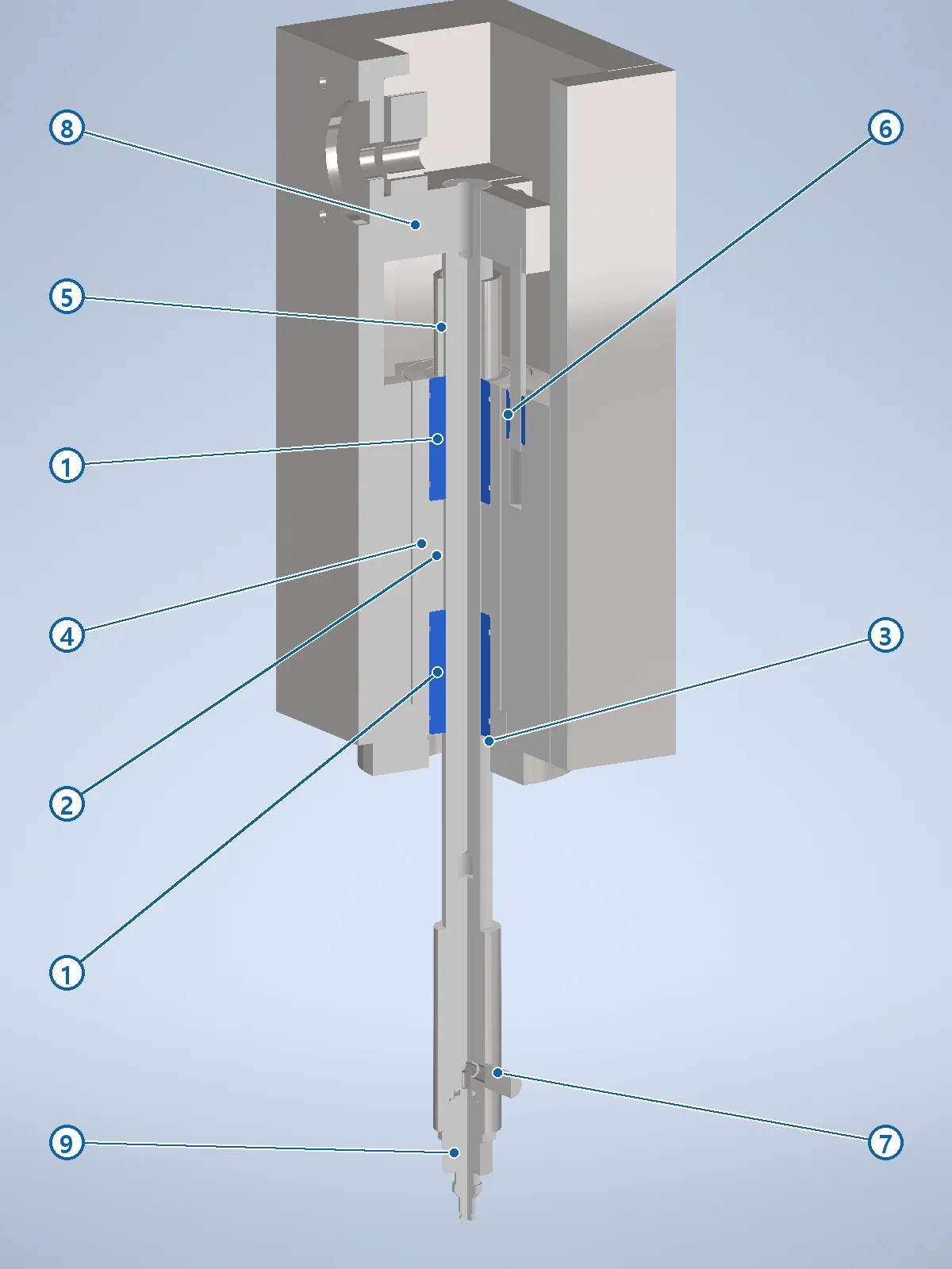
VI 08Pick head, quarter section
Concept design, issued for review before detailed design. Specifications are subject to change and dimensions are in millimetres. Servo motors and covers are hidden in some views for clarity.